
High-Current Flexible Cable
Also called high-current flexible busbar or flexible flat cable
A flexible cable system that replaces multi-splicing cable assemblies and dense bus duct on 200 A to 6,300 A routes.
- 200 A – 6,300 A, AC and DC
- 0.6/1 kV up to 8.7/15 kV, plus DC 3 kV and below
- IP68, 105 °C conductor temperature
- Cut, branch and re-route on site
Product introduction
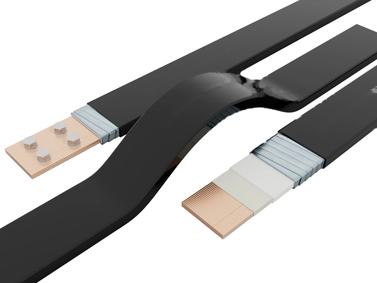
High-current flexible cable, engineered to replace bus duct
As an innovative application of high-current power transmission, the flexible cable combines traditional cable manufacturing with new materials: a high-purity copper conductor, a wrapping layer, an insulation layer, a metal armour layer and a protective sheath. It replaces multi-splicing cable assemblies, traditional busbars and bus duct in demanding field conditions.
Laying methods: Direct burial, Conduit, Cable trench, Cable tray.
Product structure
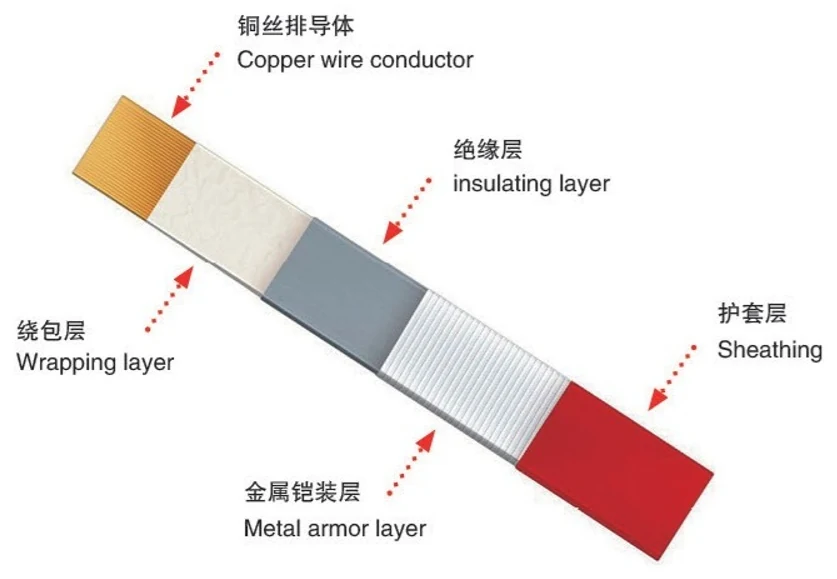
Five layers, each with a job
-
1
Copper wire conductor
High-purity copper, sized to the continuous and short-circuit duty of the route.
-
2
Wrapping layer
Binds the conductor and holds the shape of the flat profile.
-
3
Insulating layer
Withstands 105 °C conductor temperature at the rated voltage class.
-
4
Metal armour layer
Mechanical protection for buried, tray and conduit routes.
-
5
Sheathing
Outdoor-grade compound, IP68 protection, no induced voltage on the surface.
Technical requirements
Specification overview
- Specification range
- 200 A – 6,300 A
- Rated voltage
- 0.6/1 kV, 1.8/3 kV, 6/10 kV, 8.7/15 kV; DC 3 kV and below
- Rated frequency
- 50 Hz
- Protection level
- IP68
- Maximum operating temperature
- 105 °C
- Number of cores
- 4-core (A, B, C, N); 3+1 (A, B, C, N, N 50%); 5-core (A, B, C, N, PE); 3+2 (A, B, C, N, PE 50%); 4+1 (A, B, C, N, PE 50%)
Selection and technical parameters
Cable selection table
Current-carrying capacity is quoted for cable in air at an ambient temperature of 35 °C. Correction factors for buried, cable-tray and conduit installation are supplied with the technical datasheet.
| Spec (A) | Switch AT value (A) | Bend radius (mm) | Resistance (mΩ/km) | Impedance (Z 10⁻⁶Ω/m) | Voltage drop (V/m) | Short-circuit strength (kA, t=1s) | Ampacity AC (A) | Ampacity DC (A) |
|---|---|---|---|---|---|---|---|---|
| 200 | 160 | ≥200 | 94.4 | 103.8 | 0.0475 | 35 | 220 | 225 |
| 300 | 200–300 | ≥200 | 89.5 | 85.3 | 0.0455 | 40 | 325 | 330 |
| 400 | 315–400 | ≥200 | 70.8 | 83.2 | 0.041 | 50 | 430 | 440 |
| 500 | 500 | ≥200 | 71.5 | 82.7 | 0.040 | 58 | 525 | 535 |
| 630 | 630 | ≥200 | 73.0 | 72.4 | 0.038 | 65 | 645 | 675 |
| 800 | 800 | ≥500 | 61.4 | 69.8 | 0.036 | 70 | 815 | 880 |
| 1,000 | 1,000 | ≥500 | 46.6 | 53.8 | 0.032 | 85 | 1,050 | 1,090 |
| 1,250 | 1,250 | ≥500 | 28.9 | 40.6 | 0.030 | 100 | 1,275 | 1,465 |
| 1,600 | 1,600 | ≥500 | 23.6 | 38.0 | 0.028 | 115 | 1,630 | 2,035 |
| 2,000 | 2,000 | ≥1,000 | 21.3 | 24.1 | 0.026 | 129 | 2,065 | 2,685 |
| 2,500 | 2,500 | ≥1,000 | 14.4 | 19.7 | 0.024 | 135 | 2,560 | — |
| 3,200 | 3,200 | ≥1,000 | 11.9 | 16.2 | 0.021 | 150 | 3,255 | — |
| 4,000 | 4,000 | ≥1,000 | 10.8 | 12.6 | 0.019 | 135 | 4,040 | — |
| 5,000 | 5,000 | ≥1,000 | 7.50 | 10.3 | 0.017 | 175 | 5,070 | — |
| 6,300 | 6,000 | ≥1,000 | 5.95 | 7.8 | 0.0145 | 190 | 6,340 | — |
Scroll the table sideways on a phone.
Product comparison
How it performs against the alternatives
Versus multi-splicing cables
| Item | High-current flexible cable | Multi-splicing cables |
|---|---|---|
| Product performance | Consistent resistance across the run, so current is shared evenly and the cable runs cooler. | Each length has a different resistance, which causes uneven current flow and local heating. |
| Installation | Small cross-section, compact and flexible; specialist T-connectors keep the joint safe. | Large volume and weight; joints are difficult to handle and are a safety risk. |
| Current carrying capacity | One cable covers 200 A to 6,300 A. | A single cable carries little current, so high loads need several parallel runs. |
| Overall cost | High current density and clear copper savings. | Low current density; more copper and higher cost for the same duty. |
Versus dense bus duct
| Item | High-current flexible cable | Dense bus duct |
|---|---|---|
| Appearance and volume | Neat appearance, compact and easy to route. | Takes up a large amount of installation space. |
| Overload capacity | Temperature rise of 135 K at 40 °C ambient, with more than 33% overload capacity. | Temperature rise of 70 K at 30 °C ambient, with about 15% overload capacity. |
| Installation and rework | Cut, re-terminate and reconfigure on site; branches can be added while the main circuit stays energised. | Assembled in the factory; difficult to change and re-use is limited, so live branching is not possible. |
| Backup | Can be switched in as an emergency supply through a changeover box. | Needs a power outage for maintenance; supply cannot be restored quickly. |
| Energy and loss | Low temperature rise and low line loss; the advantage grows with the cable size. | Poor heat dissipation, larger losses, more than 20% higher energy consumption. |
Related accessories
Branching and changeover without breaking the run
Conversion box
Used for branching high-current cable or transferring between flexible cables, which extends the reach of the system.
Pre-branch and T-shaped connector
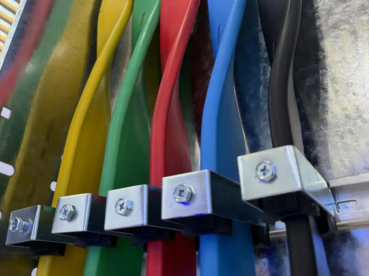
The main line runs as one integrated circuit with no intermediate joints. Where a load has to be tapped, a T-shaped connector or a pre-branched length is used. Joints are sealed to IP68.
Smart cable
Intelligent monitoring option
The cable system can be supplied with distributed temperature sensing, turning the cable itself into a monitoring device.
- Real-time measurement of maximum, minimum and average operating temperature
- Measurement and location of hot points, with ±0.2 m positioning accuracy
- Data communication to the site SCADA system, conforming to IEC 61850
- Alarms for over-temperature, rate of temperature rise, temperature difference and abnormal points
- Conductor temperature calculation and dynamic ampacity calculation
- Complete data storage, automatic backup and event identification
- Detection distance
- 2 – 16 km
- Channels
- 4, 8, 12, 16, 32
- Temperature range
- −50 °C to +650 °C (customisable)
- Temperature resolution / accuracy
- 0.1 °C / ±0.1 °C
- Supply
- 220 VAC, < 2 A
- Humidity
- < 95% RH, non-condensing
On site
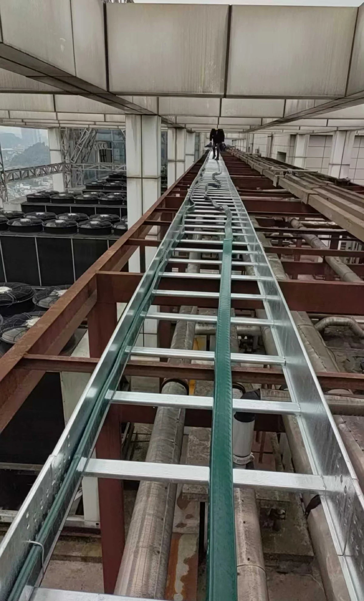
Tray, trench and conduit
One drum means one piece for the whole run — no joint in the middle of a route, and no joint to inspect five years later. These are the three routes it goes into most often.
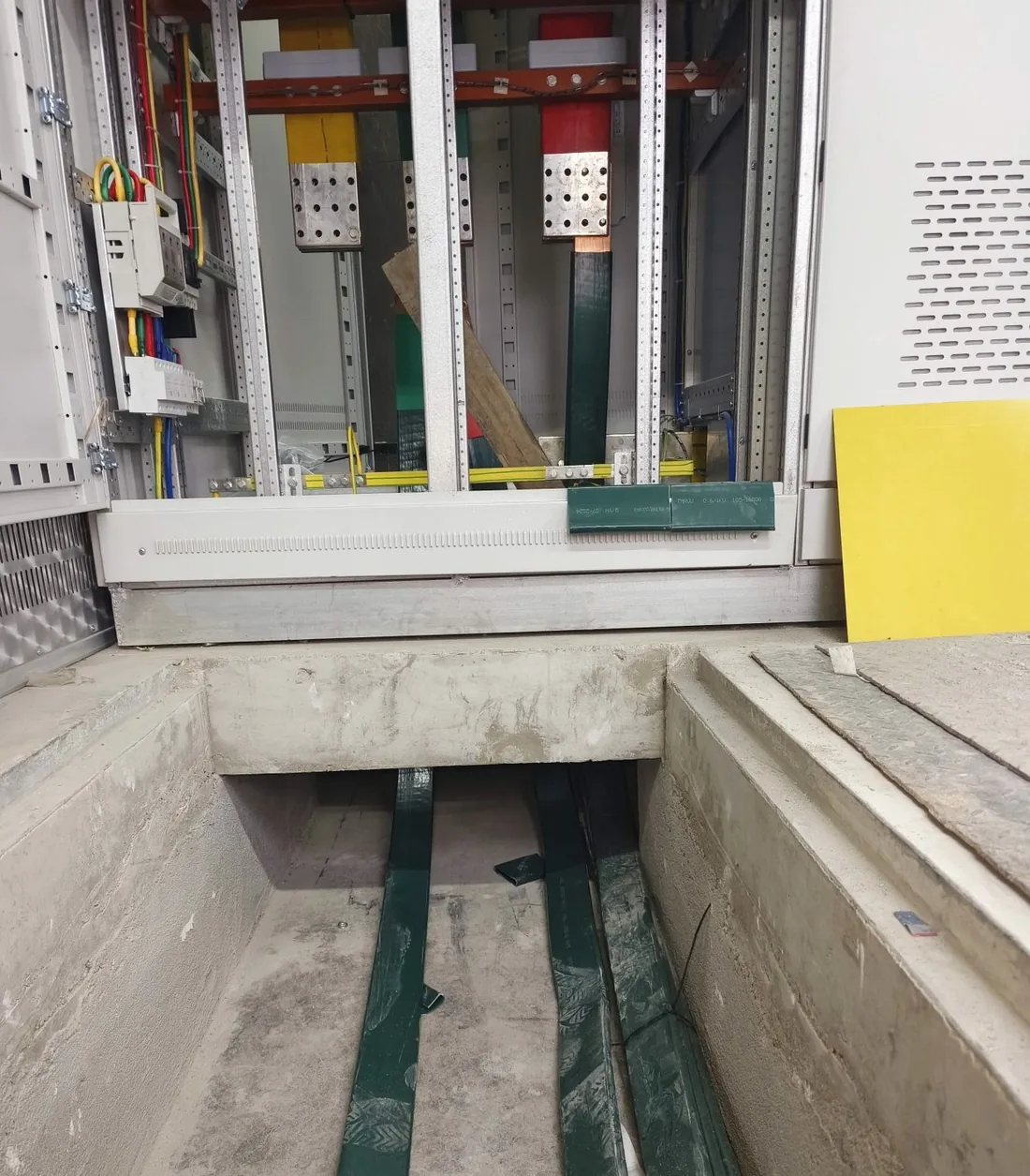
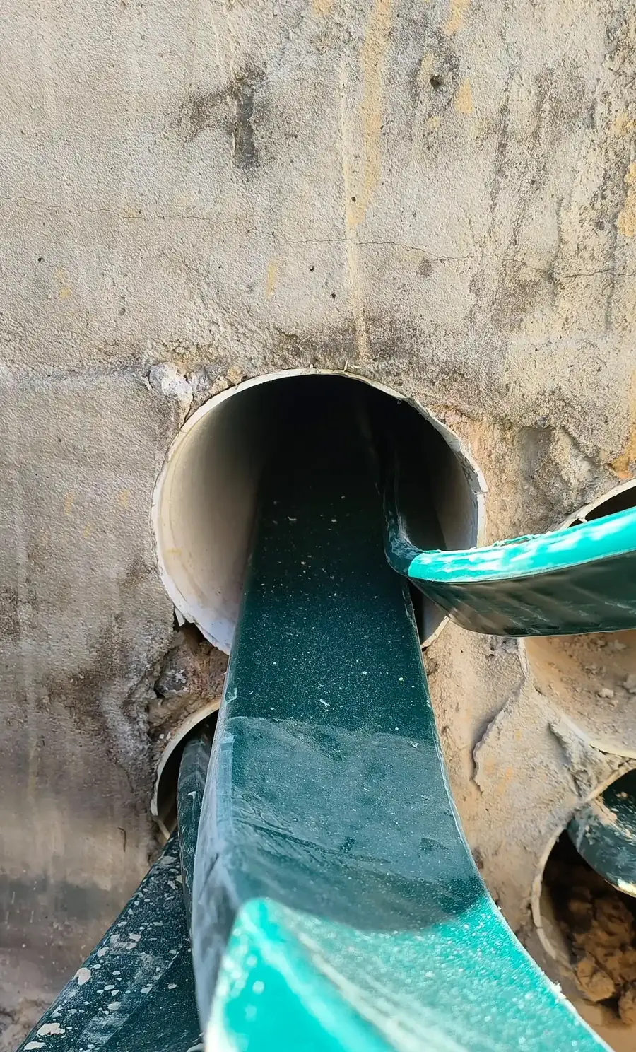
Where it is used
Typical installations
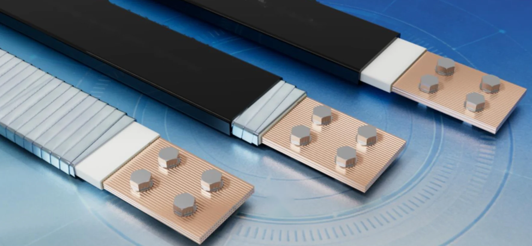
EV Super Charging Stations
Get power from the distribution room to the dispensers without a bus duct run
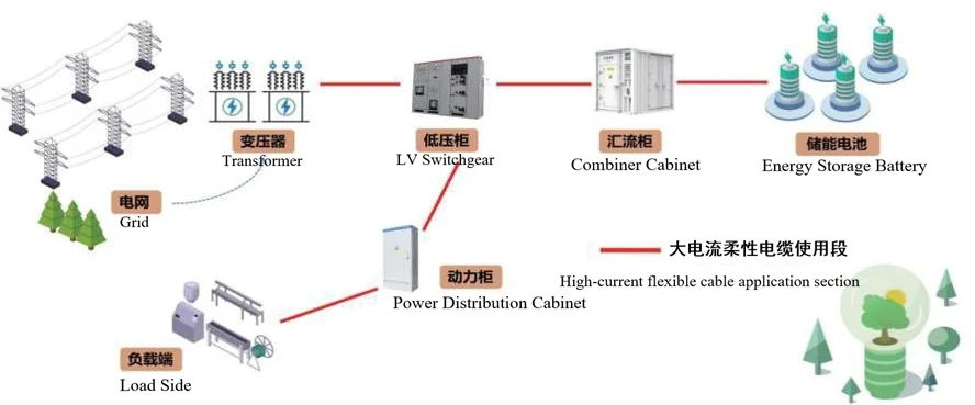
Energy Storage Systems
High current inside a small footprint
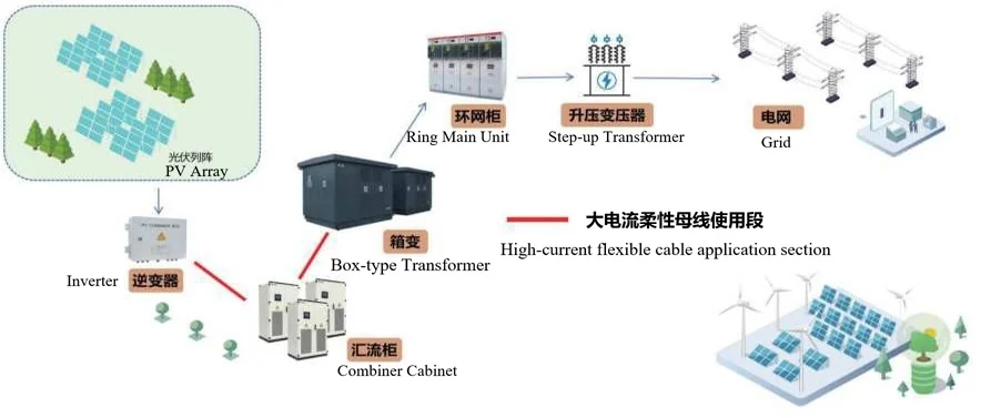
Photovoltaic Plants
Outdoor routes that survive sun, water and time
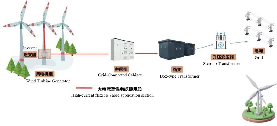
Wind Power
Flexible enough for the tower, tough enough for the coast
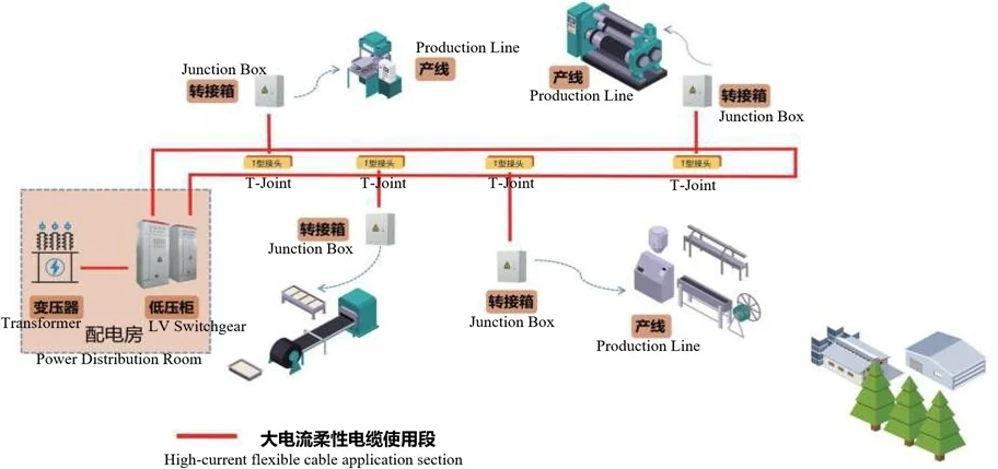
Industrial Buildings and Parks
Rework the layout without cutting the supply
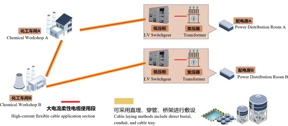
Chemical and Process Parks
Routes that can be inspected, cleaned and repaired
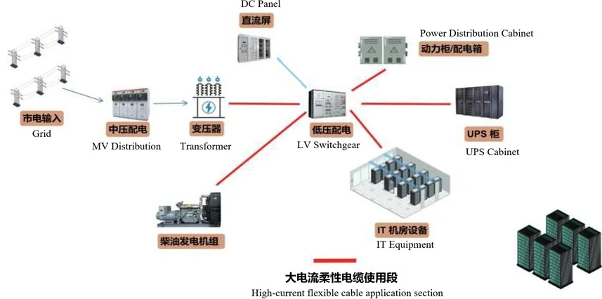
Data Centres and IDC Rooms
High current in the tightest part of the building
Send us the load and the route
Tell us the current, voltage, route length and laying method. You will have a specification, a drawing and a price within one working day.